
What we will do
In this post, I will show you how your can connect to ESP 8266 Node MCU to Firebase and how you can easily implement controlling ESP8266 Node MCU from Firebase for IOT application.
We can use any of three Node MCU to perform this test / action.
 Node MCU from Seedstudio
Node MCU from Official website
 Adafruit Huzzah Node MCU
Step 1. Solder the Pins and prepare console or FTDI cable:
We need to solder the pins that come with the PCB board. We also need aFTDI or Console cable. I used the console cable and the connection is exactly as it is shown in this Adafruit Tutorial, which I also include here as below. Console Cable Connection
If using a console cable, connect the black wire to ground, red wire to V+, white wire to TX and green wire to RX.
Step 2. Install Arduino Board Package:
Enterhttp://arduino.esp8266.com/stable/package_esp8266com_index.json into Additional Board Manager URLs field in the Arduino v1.6.4+ preferences. Then, use the Board manager to install the ESP8266 package. If you search for ESP8266 then it will show the board from board package from the ESP8266 community. Install it. Restart the Arduino IDE and select Adafruit HUZZAH ESP8266 from the Tools->Board dropdownStep 3. Create a Firebase project and get the API key
When you create Firebase project, you need to create the secret. Go to Database. There you will see the database secret. This is for the legacy database. However, we are using it for now. Becuase we are using Arduino. The right way in the system is to use the SDK. But the SDK is only available for Node.JS and Java.
Step 4: The code in the MCU:
Using Adafruit Huzzah Node MCU:Select the board "Adafruit Huzzah" in the Arduino Library and upload the code below:
#include ESP8266WiFi.h; //https://github.com/esp8266/ArduinoI used the red light as my Firebase variable. One thing you need to do to change the Firebase Database rule as we are not using any authentication for this example and we are reading the data from the Firebase in the NodeMCU.
//needed for library
#include FirebaseArduino.h;
#define FIREBASE_HOST "YOUR_FIREBASE_HOSTNAME[XXX.firebaseio.com]"
//This is your Firebase Hostname which can be found in the Firebase console.
#define FIREBASE_AUTH "YOUR_FIREBASE_SECRET"
//This is the database secret(legacy), not firebase service or web key.
#define WIFI_SSID "YOUR_WIFI_SSID"
//SSID of your ruter.
#define WIFI_PASSWORD "YOUR_WIFISSID_PASSWORD"
int ledPin = 0;
//int data=1;
void setup() {
// put your setup code here, to run once:
Serial.begin(9600);
WiFi.begin(WIFI_SSID, WIFI_PASSWORD);
// Serial.print("connecting");
while (WiFi.status() != WL_CONNECTED) {
Serial.print(".");
delay(500);
}
//if you get here you have connected to the WiFi
// Serial.println("connected...yeey :)");
Firebase.begin(FIREBASE_HOST, FIREBASE_AUTH);
//Firebase.set("redlight", 0);
pinMode(LED_BUILTIN, OUTPUT); digitalWrite(LED_BUILTIN, HIGH);
}
void loop() {
// put your main code here, to run repeatedly:
digitalWrite(LED_BUILTIN, Firebase.getInt("redlight"));
Serial.println(Firebase.getInt("redlight"));
if (Firebase.failed()) {
Serial.println(Firebase.error());
}
delay(500);
}
{
"rules": {
".read": true,
".write": "auth != null"
}
}
Now, in your Firebase Database, if you change the value like as I am changing as shown in this screenshot, you will see that the builtin-LED is going to on and off.
 Controlling built-in LED of NodeMCU from Firebase
Please remember that the LED is wired between power and pin 0. Setting the pin high puts the pin at the same voltage as the source, so no current flows. Setting the pin LOW puts it at a voltage of zero, so current flows. So, if you change the value of "redlight" variable to 1(one), it will turn off the LED. And if you put it 0(zero), it will turn on the LED. For this example, I used the Adafruit Huzzah Node MCU listed here https://amzn.to/3hNgbQh. It's a bit costly, but it works well and there is no driver issue. You can also shop it in my SHOP page. Alternatively, you can use ESP8266 Module ESP-12E NodeMcu LUA which I am gonna show what are few changes you need to make it work.
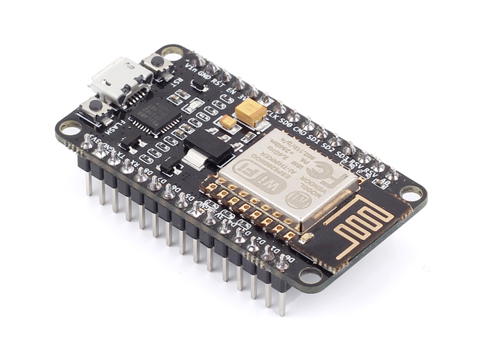
UsingESP8266 Module ESP-12E NodeMcu:
To use this, you need to use Silicon Labs's CP2102 driver software, if you use MAC. For windows it should be OK, I guess. What it means is that it uses CP2102 as UART bridge to flash firmware by using node MCU-flasher. However, I am gonna give you the link: so that it will help both for MAC and windows: http://www.silabs.com/products/mcu/pages/usbtouartbridgevcpdrivers.aspx
After you downloaded, restart the machine. And restart the Arduino IDE. You should choose Node MCU ESP 12E module and the port as /cu.SLAB_USBtoUART. The same code should also in this case. The Firebase steps and the procedure will be the same. In a later post, I will show you how you can soft config and send the SSID and password to MCU from the phone. It is needed as you or your customer (if you run an IOT company) can not always hard code the SSID in the firmware when the router configuration changes. If you want to buy the NodeMCU that I haves used, you can buy it from the SHOP. You can also use buy as here. https://amzn.to/3hNgbQh


0 Comments